


Digital baseband linear modems: M-PSK and M-QAM.
The main idea is to develop a Python module that allows replacing related to baseband digital linear modulations MatLab/Octave functions and objects. This project is inspired by CommPy open-source project.
Linear modulation schemes have a canonical form [1]:
where is the In-phase part,
is the Quadrature part,
is the carrier frequency, and
is the time moment. In-phase and Quadrature parts are low-pass signals that linearly correlate with an information signal.
Modulation scheme can also be modeled without consideration of the carrier frequency and bit duration. The baseband analogs can be used for research due to the main properties depend on the envelope (complex symbols).
Modulation order means number of possible modulation symbols. The number of bits per modulation symbol depend on the modulation order:
Modulation order relates to gross bit rate concept:
where is the baud or symbol rate. Baud rate usually relates to the coherence bandwidth
(see more in [2]).
See more in "Basics of linear digital modulations" (slides).
Released version on PyPi:
$ pip install ModulationPyTo build by sources, clone from github and install as follows:
$ git clone https://github.com/kirlf/ModulationPy.git
$ cd ModulationPy
$ python3 setup.py install- M-PSK: Phase Shift Keying
- M-QAM: Quadratured Amplitude Modulation
where M is the modulation order.
M-PSK modem is available in class PSKModem with the following parameters:
| Parametr | Possible values | Description |
|---|---|---|
M |
positive integer values power of 2 | Modulation order. Specify the number of points in the signal constellation as scalar value that is a positive integer power of two. |
phi |
float values | Phase rotation. Specify the phase offset of the signal constellation, in radians, as a real scalar value. The default is 0. |
gray_map |
True or False |
Specifies mapping rule. If parametr is True the modem works with Gray mapping, else it works with Binary mapping. The default is True. |
bin_input |
True or False |
Specify whether the input of modulate() method is bits or integers. When you set this property to True, the modulate() method input requires a column vector of bit values. The length of this vector must an integer multiple of log2(M). The default is True. |
soft_decision |
True or False |
Specify whether the output values of demodulate() method is demodulated as hard or soft decisions. If parametr is True the output will be Log-likelihood ratios (LLR's), else binary symbols. The default is True. |
bin_output |
True or False |
Specify whether the output of demodulate() method is bits or integers. The default is True. |
The mapping of into the modulation symbols is done by the following formula:
where is the phase rotation,
is the decimal input symbol, and
is the modulation order.
The input should be in range between 0 and M-1.
If the input is binary, the conversion from binary to decimal should be done before. Therefore, additional supportive method __de2bin() is implemented. This method has an additional heuristic: the bit sequence of "even" modulation schemes (e.g., QPSK) should be read right to left.
M-QAM modem is available in class QAMModem with the following parameters:
| Parametr | Possible values | Description |
|---|---|---|
M |
positive integer values power of 2 | Modulation order. Specify the number of points in the signal constellation as scalar value that is a positive integer power of two. |
gray_map |
True or False |
Specifies mapping rule. If parametr is True the modem works with Gray mapping, else it works with Binary mapping. The default is True. |
bin_input |
True or False |
Specify whether the input of modulate() method is bits or integers. When you set this property to True, the modulate() method input requires a column vector of bit values. The length of this vector must an integer multiple of log2(M). The default is True. |
soft_decision |
True or False |
Specify whether the output values of demodulate() method is demodulated as hard or soft decisions. If parametr is True the output will be Log-likelihood ratios (LLR's), else binary symbols. The default is True. |
bin_output |
True or False |
Specify whether the output of demodulate() method is bits or integers. The default is True. |
E.g., QPSK with the pi/4 phase offset, binary input and Gray mapping:
from ModulationPy import PSKModem, QAMModem
import numpy as np

modem = PSKModem(4, np.pi/4,
                 gray_map=True,
                 bin_input=True)
To show signal constellation use the plot_const() method:
modem.plot_const()
E.g. 16-QAM with decimal input and Gray mapping
modem = QAMModem(16,
                 gray_map=True,
                 bin_input=False)

modem.plot_const()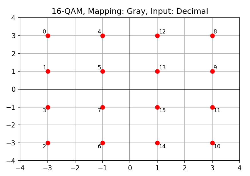
To modulate and demodulate use modulate() and demodulate() methods.
The method modulate() has the one input argument:
- decimal or binary stream to be modulated (
1-D ndarray of ints).
The method demodulate() has the two input arguments:
-
data stream to be demodulated (
1-D ndarray of complex symbols) and -
additive noise variance (
float, default is 1.0).
E.g., QPSK (binary input/otput):
import numpy as np
from ModulationPy import PSKModem

modem = PSKModem(4, np.pi/4,
                 bin_input=True,
                 soft_decision=False,
                 bin_output=True)

msg = np.array([0, 0, 0, 1, 1, 0, 1, 1]) # input message

modulated = modem.modulate(msg) # modulation
demodulated = modem.demodulate(modulated) # demodulation

print("Modulated message:\n"+str(modulated))
print("Demodulated message:\n"+str(demodulated))

>>> Modulated message:
[ 0.70710678+0.70710678j  0.70710678-0.70710678j -0.70710678+0.70710678j
 -0.70710678-0.70710678j]

 >>> Demodulated message:
[0. 0. 0. 1. 1. 0. 1. 1.]
E.g., QPSK (decimal input/otput):
import numpy as np
from ModulationPy import PSKModem

modem = PSKModem(4, np.pi/4,
                 bin_input=False,
                 soft_decision=False,
                 bin_output=False)

msg = np.array([0, 1, 2, 3]) # input message

modulated = modem.modulate(msg) # modulation
demodulated = modem.demodulate(modulated) # demodulation

print("Modulated message:\n"+str(modulated))
print("Demodulated message:\n"+str(demodulated))

>>> Modulated message:
[ 0.70710678+0.70710678j -0.70710678+0.70710678j  0.70710678-0.70710678j
 -0.70710678-0.70710678j]

 >>> Demodulated message:
[0, 1, 2, 3]
E.g., 16-QAM (decimal input/output):
import numpy as np
from ModulationPy import QAMModem

modem = PSKModem(16,
                 bin_input=False,
                 soft_decision=False,
                 bin_output=False)

msg = np.array([i for i in range(16)]) # input message

modulated = modem.modulate(msg) # modulation
demodulated = modem.demodulate(modulated) # demodulation

print("Demodulated message:\n"+str(demodulated))

>>> Demodulated message:
[0, 1, 2, 3, 4, 5, 6, 7, 8, 9, 10, 11, 12, 13, 14, 15]Let us demonstrate this at example with the following system model:
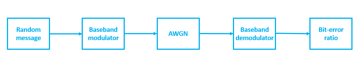
Fig. 1. The structural scheme of the test communication model.
The simulation results will be compared with theoretical curves [3]:
where ,
denotes the complementary error function,
is the energy per one bit, and
is the noise spectral density.
In case of BPSK and QPSK the following formula should be used for error probability:
The source code of the simulation is presented bellow:
import numpy as np
from ModulationPy import PSKModem

def BER_calc(a, b):
    num_ber = np.sum(np.abs(a - b))
    ber = np.mean(np.abs(a - b))
    return int(num_ber), ber

def BER_psk(M, EbNo):
    EbNo_lin = 10**(EbNo/10)
    if M > 4:
        P = special.erfc(np.sqrt(EbNo_lin*np.log2(M))*np.sin(np.pi/M))
            / np.log2(M)
    else:
        P = 0.5*special.erfc(np.sqrt(EbNo_lin))
    return P

EbNos = np.array([i for i in range(30)]) # array of Eb/No in dBs
N = 100000 # number of symbols per the frame
N_c = 100 # number of trials

Ms = [4, 8, 16, 32] # modulation orders

''' Simulation loops '''

mean_BER = np.empty((len(EbNos), len(Ms)))
for idxM, M in enumerate(Ms):
    print(M)
    BER = np.empty((N_c,))
    k = np.log2(M) #number of bit per modulation symbol

    modem = PSKModem(M,
                 gray_map=True,
                 bin_input=True,
                 soft_decision=False,
                 bin_output=True)

    for idxEbNo, EbNo in enumerate(EbNos):
        print(EbNo)
        snrdB = EbNo + 10*np.log10(k) # Signal-to-Noise ratio (in dB)
        noiseVar = 10**(-snrdB/10) # noise variance (power)

        for cntr in range(N_c):
            message_bits = np.random.randint(0, 2, int(N*k)) # message
            modulated = modem.modulate(message_bits) # modulation

            Es = np.mean(np.abs(modulated)**2) # symbol energy
            No = Es/((10**(EbNo/10))*np.log2(M)) # noise spectrum density

            noisy = modulated + np.sqrt(No/2)*\
              (np.random.randn(modulated.shape[0])+\
              1j*np.random.randn(modulated.shape[0])) # AWGN

            demodulated = modem.demodulate(noisy, noise_var=noiseVar)
            NumErr, BER[cntr] = BER_calc(message_bits,
                                            demodulated) # bit-error ratio

    mean_BER[idxEbNo, idxM] = np.mean(BER) # averaged bit-error ratio


''' Theoretical results '''

BER_theor = np.empty((len(EbNos), len(Ms)))
for idxM, M in enumerate(Ms):
    BER_theor[:, idxM] = BER_psk(M, EbNos)


''' Curves '''

fig, ax = plt.subplots(figsize=(10,7), dpi=300)

plt.semilogy(EbNos, BER_theor[:,0], 'g-', label = 'QPSK (theory)')
plt.semilogy(EbNos, BER_theor[:,1], 'b-', label = '8-PSK (theory)')
plt.semilogy(EbNos, BER_theor[:,2], 'k-', label = '16-PSK (theory)')
plt.semilogy(EbNos, BER_theor[:,3], 'r-', label = '32-PSK (theory)')

plt.semilogy(EbNos, mean_BER[:,0], 'g-o', label = 'QPSK (simulation)')
plt.semilogy(EbNos, mean_BER[:,1], 'b-o', label = '8-PSK (simulation)')
plt.semilogy(EbNos, mean_BER[:,2], 'k-o', label = '16-PSK (simulation)')
plt.semilogy(EbNos, mean_BER[:,3], 'r-o', label = '32-PSK (simulation)')

ax.set_ylim(1e-7, 2)
ax.set_xlim(0, 25.1)

plt.title("M-PSK")
plt.xlabel('EbNo (dB)')
plt.ylabel('BER')
plt.grid()
plt.legend(loc='upper right')
plt.savefig('psk_ber.png')
It works. Well done.
- Haykin S. Communication systems. – John Wiley & Sons, 2008. — p. 93
- Goldsmith A. Wireless communications. – Cambridge university press, 2005. – p. 88-92
- Link Budget Analysis: Digital Modulation, Part 3 www.AtlantaRF.com